Routes
The Route options allow users to configure settings related to routes behavior and appearance.
-
Route Color: changes the default Route color.
-
Route Thickness: changes the thickness of all routes. This is a global setting that will affect all the routes displayed on the screen.
-
Display Route Wizard after creating a route: check this option to have the software display the Route Wizard when a route is created. The Route Wizard can also be displayed by right clicking on a Route and select "Open Route Wizard".
-
Great Circle Navigation: when this option is checked, the software will compute and display distance (with the divider tool) using the Great Circle distance (shortest distance between points on the surface of the Earth). The software will also chop long routes in smaller segments along the great circle path. These shorter resulting legs can be considered as straight ("rhumb line") segments that follow the shortest path on a Mercator projection using fixed bearing (on each segment).
-
Route Auto Zoom: when this option is checked, the software will automatically adjust the zoom level when a new Waypoint is activated along a route. The software will either zoom in or zoom out in order to show the current position and the next Waypoint.
Note: The Route Auto Zoom will only work if the boat is displayed on the screen (the software will not attempt to adjust the zoom level if you are panning on another area) -
Route Animation: when this option is checked, an animation is displayed on the active and planning route indicating its direction. If you find the animation distracting, you can turn OFF this option.
-
Display XTE Alarm Lines: when this option is checked, a red and green dash line (respectively port and starboard) will appear on each side of the active leg (when a route is activated). These lines are a graphical representation of the Cross Track Alarm value.
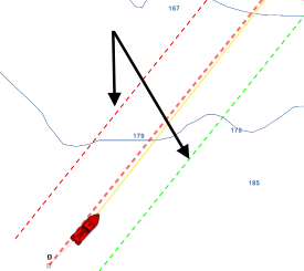
Note: In order to see the XTE Alarm Lines on the chart, you may have to zoom in at a closer range -
Default Route XTE Value: this setting sets the default value of the route cross track error (used for displaying the XTE Alarm lines). Note that if the "Automatic XTE" setting is turned ON, the value used on a route leg might be inferior according to the Route Safety check.
-
Check Route Safety: this setting enables TimeZero to scan for dangerous objects and depth area along any route that has been created. Please refer to Route Safety for more information.
-
Automatic XTE: When this setting is enable, TimeZero is allowed to reduce the XTE value of each leg to avoid obstacle (related to Route Safety). The minimum acceptable value is set by adjusting the Minimum XTE Value setting below
-
Minimum XTE Value: When Automatic XTE is enabled, TimeZero can reduce the XTE value down to this minimum value. Set this setting to the absolute minimum XTE value you are comfortable with.
-
Prevent Creating Route when Leg is unsafe: When this setting is enabled, you will not be able to drop a waypoint until the leg of the route you are building has been analyzed and considered safe (using the Route Safety parameters).
-
Route Safety Configuration: Click this button to adjust the type of objects that will be checked for the Route Safety and Anti-Grounding Cone. You can also enter your safety depth (for depth sounding and depth area) and safety height (for bridge clearance).
-
Waypoint Switching Mode: this setting determines how the software switches to the next Waypoint automatically in a route. Please refer to the Waypoint Switching Mode chapter for more explanation about the 3 modes below:
-
-
Circle: in this mode, the next Waypoint is automatically switched when your boat icon enters the active Waypoint's switching circle
-
Cross Line (also known as "perpendicular"): in this mode, the next Waypoint is automatically switched when your boat crosses the line through the Waypoint that is perpendicular to the active leg line
-
Circle and Cross line: in this mode, the next Waypoint is automatically switched if it enters the switching circle or crosses the line
-
Wheel Over Mode: in this mode, the next Waypoint is automatically switched at the computed Wheel Over Point, based on the route geometry, vessel speed, and Rate of Turn
-
-
Switching Circle Radius: this option sets the radius of the switching circle and arrival alarm. This is a global setting that affects all Waypoints in a route.
-
Intelligent Waypoint Centering: when this option is checked, the chart will automatically pan when a route is being built.
-
Display Leg Distance and Bearing: when this option is checked, the distance and bearing (course to steer) will be displayed on the route leg:

Note: the distance and bearing are not displayed on the active leg. This information can be displayed in the NavData using the "Route NavData" -
Route Planning Default Speed: Set the default speed that will be used when creating a route.
-
Rate of Turn: Set the vessel’s turning capability, expressed in degrees per minute, and is used by Wheel Over Mode to calculate the Wheel Over Point and the turning arc. For more information about the Wheel Over Mode, please refer to the Waypoint Switching Mode chapter.
-
Use Currents in Active Route: when this option is checked, TimeZero enables current computation on the Active Route. Note that you may want to leave this option disabled if you do not have an accurate speed through water sensor connected to the computer, or if you want the route computation (ETA, TTG,...) to match other devices on your vessel that are not able to take currents into account.
Note: This option may slow down the software on an older computer.
Route Assist:
-
Safety Depth: set the safety depth value that is used by the Route Assist algorithm.
-
Strict Depth Compliance: select this option if you want Route Assist to strictly respect the safety depth.
-
Use Vector Charts Recommended Route: select this option if you want Route Assist to follow the recommended routes that are provided by the hydrographic offices and included in the charts "crowd-sourced recommended routes" come from user-contributed data.
-
Use Crowd Source Recommended Route: select this option if you want Route Assist to follow the recommended routes that come from user-contributed data.
Fuel:
-
Fuel: Fuel options are used to configure the display of estimated maximum fuel range calculations within the TimeZero software. Fuel tank levels and fuel flow information come from NMEA2000 sensors (or J1939 sensors that are converted to NMEA2000 data streams)
-
-
Show Max Range on Route: this option turns on or off the display of the estimated maximum fuel range overlay on a Route line.
-
Max Range On Route Color: allows the user to change the color of the maximum fuel range overlay on a Route line.
-
Show Vessel Fuel Range Ring: this option turns on or off the display of the estimated maximum fuel range ring (a range ring centered around the vessel)
-
Vessel Fuel Range Color: allows the user to change the color of the maximum fuel range ring.
-
Use First (Second, Third or Fourth) Fuel Tank In Vessel Calculations: allows the user to decide to use the First, Second, Third or Fourth fuel tanks on their vessel for purposes of calculating estimated maximum fuel range
-
-
SAR Interval: Search and Rescue (SAR) Interval value for auto routing density. Values can be manually entered, or if the user uses the SAR Interval Table, the value will be automatically populated with a distance appropriate for the search conditions.
-
SAR Interval Table: Open a window that allows you to automatically set the optimum distance in between SAR path according to visibility and the type of object to look for.