FAR 3xx0 Connection
Connection
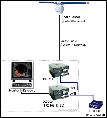
The FAR3xx0 Series Radar from Furuno consists of a:
-
Radar Sensor (Gearbox and Antenna) mounted on a Tower
-
Radar Cable (Power & Ethernet)
-
EC3000 Processor Box (with LAN1 / LAN2 / LAN3 Ethernet Output)
-
Dedicated Keyboard and Service Monitor
When connecting a FAR3K series radar to TimeZero for Coastal Monitoring application, it is not mandatory to connect GPS, Heading or AIS sensor to the FAR processor box because the ARPA targets will be generated inside the software and the AIS are monitored inside the software. HOWEVER, if you want the FAR3K ACE feature to work, you will have to connect position and heading (even fixed) to the Radar.
The FAR radar and the computer need to be connected on the same local network using the IP network 192.168.31.x / 255.255.255.0. The computer MUST be connected to the LAN1 output of the EC3000 (LAN3 is reserved for the Radar Sensor connection and LAN2 is reserved for Furuno Sensor Adapter which are usually not used in Coastal Monitoring application). It is NOT possible to have a router in between the EC3000 and the computer (the EC3000 and Computer need to be on the same broadcast domain).
Ethernet Network
If the FAR3K and computer are located close to each other, they can be directly networked using a regular Cat6 Ethernet cable:
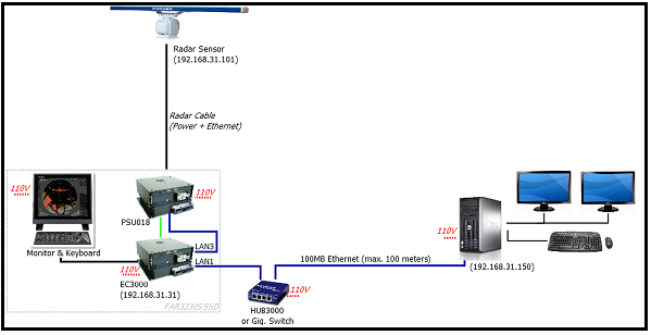
Note that the maximum length for a network cable segment is 100 meters per TIA/EIA 568-5-A. If longer runs are required, the use of active hardware such as a repeater or switch is necessary. Usually, fiber optic media is recommended for longer run than 100 meters.
Fiber Optic
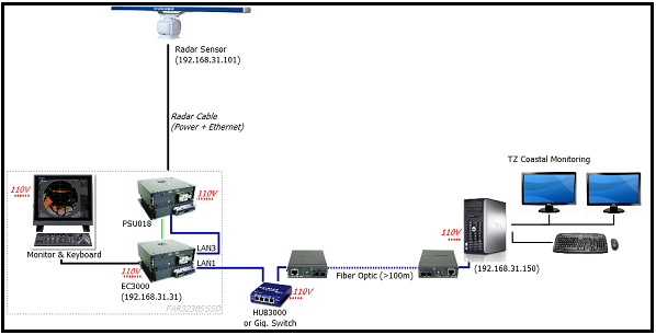
A regular Ethernet network can be easily extended using fiber optic media converters if one run needs to be longer than 100 meters (usually in between the radar tower and the computer):
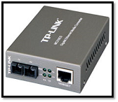
The below diagram shows a configuration where a pair of fiber to Ethernet converters are used to extend the run using fiber optic cable:
Check and Assign Radar Hostname(s)
When multiple radars are networked or inter-switched together via LAN1, a unique "Equipment ID" (and IP address) must be assigned to each processor and radar sensor antenna. Note that for TimeZero to correctly detect the radar, at least one Radar Sensor Unit must be assigned to 192.168.31.101.
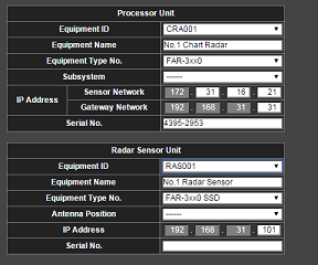
IMPORTANT: When changing the Equipment ID for the EC3000 (Processor Unit), it is important to also have the Radar Sensor unit connected to LAN3 of the EC3000. Changing the Processor Unit ID will also change the Radar Sensor Unit ID (so that they match). If you change the Processor Unit ID without the Radar sensor connected, you may introduce a mismatch in between the Radar Sensor ID and the Processor ID.
Please refer to the Furuno Radar Installation Manual to properly setup the IP addresses.
FAR3xx0 Initial Settings
The Radar Initial setup is performed from the Radar Keyboard and service monitor or a web browser on 192.168.31.31. Please refer to the Furuno Radar Installation Manual to properly setup the FAR radar.
Configure the computer
TimeZero connects to a Furuno FAR 3XX0 radar through an Ethernet connection (100Base-T) on LAN1 of the EC3000. The computer needs to have an IP address that “matches” the Radar Network (192.168.31.x / 255.255.255.0). We highly recommended using 192.168.31.150 as a fix IP address for the computer with a subnet mask of 255.255.255.0.
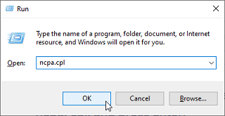
Open the "Network Connections" control panel of your computer to adjust the IP address. Under Windows 10/11 you can press the combination shortcut Windows Key + R to open the Run dialog box. Type "ncpa.cpl" and click on "OK":
Double click on the Network Adapter connected to the radar (usually “Local Area Connection”).
Note: If you have multiple Area Connections (multiple Ethernet Cards) and if you don’t know which one is connected to the radar, you can temporarily disconnect the Ethernet Cable connected to the radar from the computer and look at which icon will display a red cross. This will indicate the LAN that has been disconnected from the computer, and thus the one that needs to be configured.
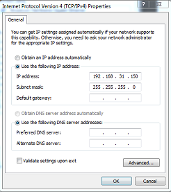
Select "Properties" on the "Local Area Connection Status" window. Double click on “Internet Protocol Version 4 (TCP/IPv4)”. Use the fix IP address 192.168.31.150 with a subnet mask of 255.255.255.0:
Once the computer's IP address has been assigned, it is recommended to Ping the IP address of the Radar Sensor Unit (192.168.31.101) to make sure the network is correctly set up. For more information on how to ping an Ethernet device, refer to the How To Ping chapter. Once connectivity has been confirmed, launch TimeZero.
TimeZero Initial Setup
Select the Radar Options. Under "Radar Initial Setup", select the FAR Host Name you want to configure and adjust the following settings:
-
enter the antenna position (Lat/Lon)
-
enter the antenna orientation. You can use the Radar Overlay on the chart to help setting the orientation of the radar
If you have two radars connected to TimeZero, please refer to the Dual Radar Setup chapter.