Direct DRS Connection
Power Supply Unit Connection (optional on some models)
Some newer DRS (such as the DRS-NXT) do not need any Power Supply Unit and can be connected directly to DC 24v and in some case DC 12v. Other models may come with a power supply unit (PSU-xxx). Please refer to your Furuno DRS installation guide for more information about power connection.
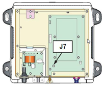
If the DRS model you use requires the PSU012 or PSU013 (Power Supply Unit) to power the antenna (48v), make sure to insert the “J7” jumper inside the PSU (under its cover). If the jumper is not inserted, the PSU will not power ON (the LED will remain OFF) even when 12 or 24v is provided:
Network Connection
The DRS radar and the computer needs to be connected on the same local network using the Furuno IP address (172.31.x.x / 255.255.0.0). It is NOT possible to have a router in between the DRS radar and the computer (the DRS and Computer need to be on the same broadcast domain).
Ethernet Network
If the DRS and computer are located close to each other, they can be networked using regular Cat5e or Cat6 Ethernet cable:
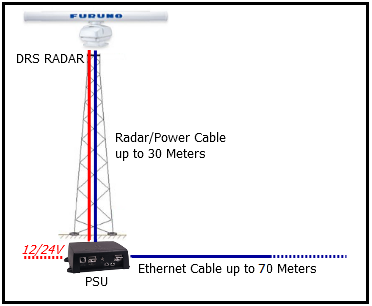
Note that the maximum length for a network cable segment is 100 meters per TIA/EIA 568-5-A. If longer runs are required, the use of active hardware such as a repeater or switch is necessary. Usually, fiber optic media is recommended for longer run than 100 meters.
Fiber Optic
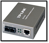
A regular Ethernet network can be easily extended using fiber optic media converters if one run needs to be longer than 100 meters (usually in between the radar tower and the computer):
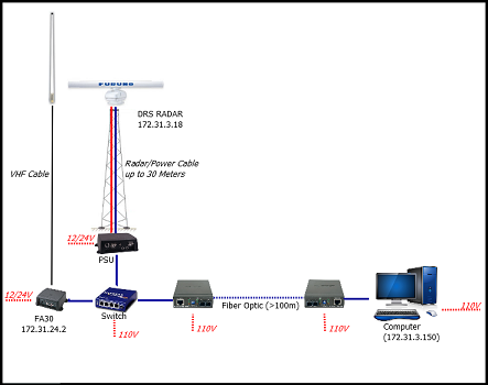
The below diagram shows a configuration with a DRS and AIS receiver connected to a switch at the base of the tower. A pair of fiber to Ethernet converters are used to extend the run using fiber optic cable:
Wireless Line of Sight bridge
In cases where Ethernet cable or Fiber Optic are not practicable, it is possible to use a dedicated Wireless Line of Sight bridge consisting of two antennas. Please note that the wireless link must support 30Mbps at minimum in order to carry the radar signal. The pair of antennas must be configured as a transparent bridge (they must act like an Ethernet cable without any routing or filtering):
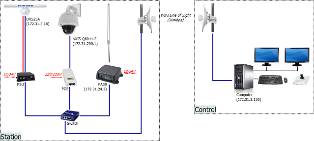
Solutions like the Motorola PtP250 and Ubiquity NanoBridge can create wireless link up to 3KM (at 30Mbps).
IMPORTANT: The signal path in between the two antennas must be absolutely clear from any obstacle (trees, buildings, etc...)
Set the IP of the Computer
The computer needs to have an IP address that “matches” the Furuno Network (172.31.x.x/255.255.0.0) in order to exchange information with the DRS. We highly recommended using 172.31.3.150 as a fixed IP address for the computer with a subnet mask of 255.255.0.0.
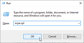
Open the "Network Connections" control panel of your computer to adjust the IP address. Under Windows 10/11 you can press the combination shortcut Windows Key + R to open the Run dialog box. Type "ncpa.cpl" and click on "OK":
Double click on the Network Adapter connected to the radar (usually “Local Area Connection”).
Note: If you have multiple Area Connections (multiple Ethernet Cards) and if you don’t know which one is connected to the radar, you can temporary disconnect the Ethernet Cable from the computer and look at which icon will display a red cross. This will indicate the LAN that has been disconnected from the computer, and thus the one that needs to be configured.
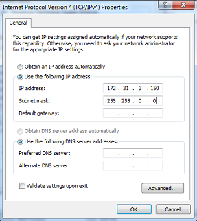
Select "Properties" from the "Local Area Connection Status" window. Double click on “Internet Protocol Version 4 (TCP/IPv4)”. Use the fixed IP address 172.31.3.150 with a subnet mask of 255.255.0.0:
Once the computer's IP address has been assigned, launch TimeZero.
Note: Make sure the DRS is turned ON before starting TimeZero. TimeZero will not display the Radar features if the DRS is turned OFF or not present on the network.
DRS Initial Setup
Perform the DRS Initial Settings from the Radar Options in TimeZero. Under "Radar Initial Setup", select the DRS Hostname you want to configure and adjust the following settings:
-
enter the antenna position (Lat/Lon) and orientation. You can use the Radar Overlay on the chart to help setting the orientation of the radar
-
enter the antenna height
-
optional: setup the blank sector to avoid sending electromagnetic energy in area that don't need to be covered by the radar (toward land for example)
If you have two radars connected to TimeZero, please refer to Dual Radar Setup.