Augmented Reality
Various Augmented Reality features can be enabled from the "Augmented Reality" button located in the ribbon (when the camera has been setup for Augmented Reality):
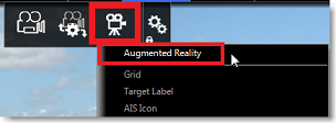
Note: Augmented Reality is available with a fixed or PTZ camera. Although it will work with just position and heading data, it is highly recommended to connect a Furuno Satellite Compass (such as SC30, SC33 or SCX20) so that compensation can be applied with Pitch and Roll data. Please refer to the setup instructions below.
Augmented Reality Layers
Grid
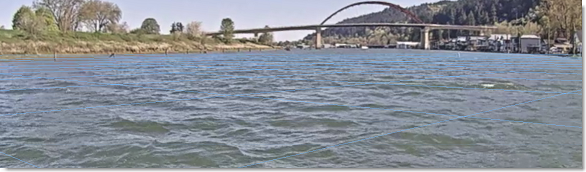
A thin blue grid can be displayed over the video:
Target Label
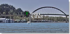
A target label can be enabled to display information of ARPA or AIS targets directly into the camera feed. It displays the relative direction of the target, its ID (in case of ARPA) or Name (in case of AIS) and its speed:
AIS Icon
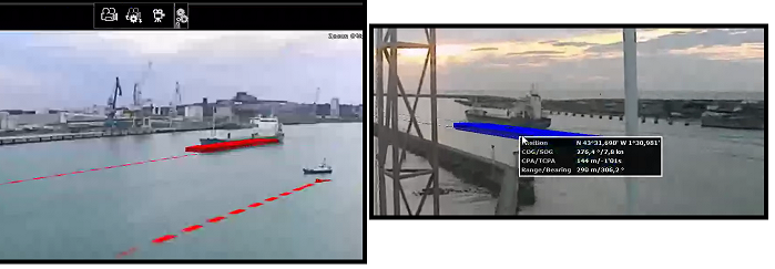
For AIS targets, TimeZero can display the icon and "shape" (if the AIS target transmits its size) directly over the video:
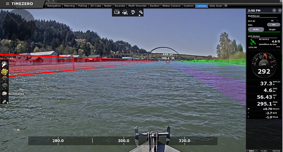
Active Route and XTE Alarm line
If you activate a route, TimeZero can display the route (in purple), the active waypoint (with distance and bearing information) and the cross track error alarm line:
TIPS: The XTE alarm line height can be setup under "Advanced Settings and Calibration" (last selection of the "Augmented Reality" button)
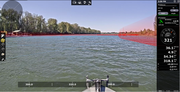
Depth Area Under Safety Depth
The vector chart depth area information can be used and displayed in the camera feed as virtual wall:
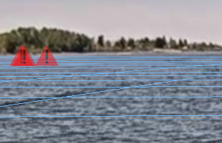
Anti-Grounding Danger
When the Anti-Grounding cone is activated (refer to the Anti-Grounding Cone chapter for more information), isolated danger can also be displayed on the camera feed
Azimuth, Pitch and Distance Scale
Various scales can be enabled or disabled at the bottom (azimuth) and right side (Pitch or Distance) of your screen. Note that it is not possible to display at the same time the Pitch and Distance scale.
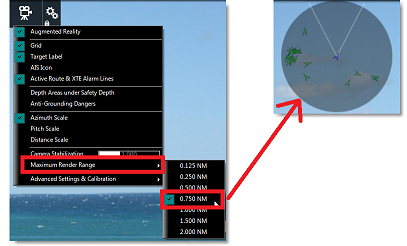
Render Range
Objects that are displayed in the Camera WorkSpace are filtered by range. You can set how far TimeZero should render objects by adjusting the setting "Maximum Render Range". Note that this range is also used by the field of view preview panel located on the upper left corner of the screen:
Stabilization
When a Pitch & Roll sensor such as the Furuno SC30, SC33 or SCX20 is connected to the computer and configured inside the Connection Wizard, TimeZero uses that information to stabilize objects (grid, target label, ...) inside the Camera WorkSpace.
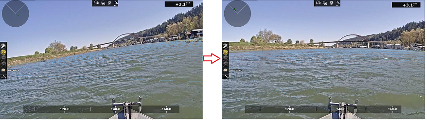
TimeZero will also display the horizon perfectly flat on your screen (using the roll data to rotate the picture of the camera). This setting is turned ON by default (located under the "Augmented Reality" button, "Advanced Settings and Calibration", "Flat Horizon"):
Finaly TimeZero can perform a digital stabilization of the entire camera picture and "smooth" abrupt changes. You can adjust the stabilization factor using the "Camera Stabilization" slider located under the "Augmented Reality" button.
Augmented Reality Setup
At minimum GPS and Heading need to be configured, but it is highly recommended to connect a Furuno Satellite compass via NMEA2000 (using the Actisense NGT-1 or NGX-1 USB). A Furuno Satellite Compass will not only provide very accurate position and heading, but it will also sent to TimeZero Pitch and Roll data. When Pitch and Roll data are configured in the Connection Wizard, TimeZero will automatically use them for stabilization.
Camera Configuration
Make sure to select "Enable Augmented Reality" when configuring the camera. With a generic H264 camera or an Axis camera, it is very important to enter the horizontal Field of View of the camera into the "FOV" field of the camera setting. When configuring a PTZ Camera, you have to enter the maximum FOV (when zoomed all the way out) and minimum FOV (when zoomed all the way in). This information can be found in the camera documentation.
Note: There is no need to enter a FOV for FLIR Camera as it is configured automatically.
Initial Adjustments (calibration)
Good calibration is very important to display properly and accurately the various augmented reality layers. To calibrate the camera, select the Camera WorkSpace, click on the "Augmented Reality" button, then select "Advanced Settings and Calibration", and then "Calibrate Camera...".
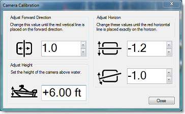
When calibrating the camera, a heading and horizon reference lines are displayed and the following window appears:
Note: If you are calibrating a PTZ camera, the camera automatically moves into the forward direction when the window is open so that you can align it with the bow of the vessel. Do NOT manually Pan/Tilt the camera when performing the calibration.
First, setup the height of the camera (its height above water) and then use the heading line (forward direction), Horizon and Rotation offset controls to calibrate the camera. To adjust the forward direction, the best is to align the vertical reference line with the bow of your vessel (if it is visible). If it is not visible, you can use an AIS target and make sure that the target label is aligned vertically with the vessel you see through the camera. To adjust the horizontal and rotational offset, the best is to have the horizon visible on screen. Then, use the two controls so that the horizon reference line matches the horizon as seen through the camera.
Sensor Delay
Some cameras may take longer than other processing data (encoding and transferring the video over the network). Also, according to your computer CPU, decoding the camera video feed might also add some lag to the overall process. In order to better "synchronize" the sensor data (heading / pitch / roll) with the video feed, it is possible to introduce a lag to the Heading and Pitch/Roll data by adjusting "Heading Delay" and "Pitch & Roll Delay" available under "Advanced Settings and Calibration".