Radar WorkSpace
The "Furuno Radar Module" needs to be unlocked and radar configured to access this feature
Radar Overview
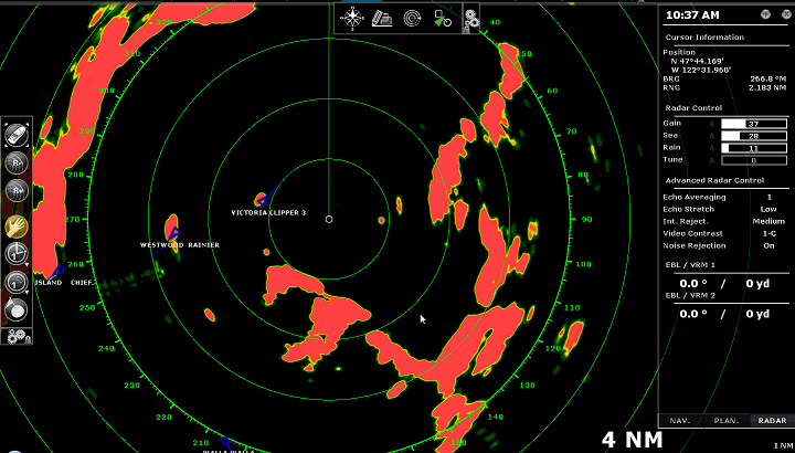
The Radar WorkSpace displays a traditional dedicated radar display:
The Radar can be displayed full screen or split screen with another display (such as Plotter).
When using a DRS radar that is capable of dual range, the Radar WorkSpace will always display the first range of the DRS. In order to display the two Radar Ranges of the DRS, a Dual Radar WorkSpace must be selected.
Transmit /Standby
When the Radar is powered on and warmed up, you can view the radar image on screen by putting the Radar in Transmit mode. You can transmit the radar by:
-
selecting the "Transmit" options from the "Radar" Ribbon button
-
by clicking on the "Stand-By" text located at the center of the radar screen
-
by clicking on the Radar Range Scale on the lower right of the screen (on the "StdBy" status)
To stop the Radar, you can:
-
uncheck "Transmit" from the "Radar" Ribbon
-
click on the "TX" located on the Radar Range Scale on the lower right of the screen.
Note that in Standby mode, the Radar is still ON but does not rotate and does not send magnetic pulses. Usually a Radar is never turned completely off in navigation because it takes a while to warm-up (1 to 2 minutes).
Radar Range
Press the radar “Range +" or "Range -" buttons located in the Toolbar to increase or lower the radar range respectively:
![]() Click this button to reduce the Range of the radar. A smaller range provides greater detail of the radar echoes close to your position (by using shorter pulse length), and should be used as you approach coastlines, harbors or if you want to monitor other vessels in your close proximity.
Click this button to reduce the Range of the radar. A smaller range provides greater detail of the radar echoes close to your position (by using shorter pulse length), and should be used as you approach coastlines, harbors or if you want to monitor other vessels in your close proximity.
![]() Click this button to increase the Range of the radar. A bigger range provides greater distance of detection, but decreases the resolution (because a longer pulse length is used by the radar).
Click this button to increase the Range of the radar. A bigger range provides greater distance of detection, but decreases the resolution (because a longer pulse length is used by the radar).
You can also use the scroll wheel of your mouse on the Radar WorkSpace to change the range (similar to zooming in or out on the chart) when the "Change Radar Range with Scroll Wheel" is checked from the Radar Options.
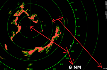
When you change the radar range, the range rings are updated on the display. The range of the Radar and the range of Ring interval are displayed on the lower right of the screen:
The range ring and interval rings can be shown or hidden from the "Radar" Ribbon button by selecting or deselecting the "Radar Rings" option. You can setup the number of interval rings displayed on the radar from the Radar Options.
Note: When you set the radar to a specific range (3NM for example), the Radar will actually transmit and detects targets farther than this value. This is done to allow the user to offset the radar (shift the display) by panning the radar screen down.
Radar Orientation
-
North Up: This mode displays the North at the top of the screen. In order to display the Radar in North Up mode on the Radar WorkSpace, a heading sensor is required.
-
Head Up: This mode orients the bow of the vessel to the top of the screen. This is the default and traditional radar orientation display.
-
Course Up: This mode is only available when a "Go To" or Route has been activated and when a heading sensor is connected to the computer. When this mode is selected, the radar screen rotates and aligns vertically with the active leg.
Bearing Scale
The Bearing Scale is displayed on the Range Ring and indicates bearing using graduations. The bearing scale can be setup in "True" or "Relative" from the Radar Options.
When set to "Relative", the bearing origin (0) is from the bow of the vessel. This means that in "Head Up" orientation mode, the bearing "0" is always at the top of the screen.
When set to "True" the bearing origin (0) is toward True North. This means that in "North Up" orientation mode, the bearing "0" is always at the top of the screen.
Note: When set to True, the bearing scale does not take into account the Magnetic Variation. It is always referenced to true North.
Range and Bearing to target
The range and bearing to a target can be measured inside TimeZero by using the Cursor NavData displayed by default in the NavData panel.
Variable Range Marker and Electronic Bearing line can also be used. Please refer to the EBL & VRM chapter for more information.
Radar Display
The Radar background and Radar echo color can be adjusted from the Radar Options.
The Radar display can be configured to not only show the radar picture but also other information such as AIS targets, Marks, Boundaries, Routes, etc...
To configure the Radar display, simply use the corresponding Ribbon buttons (Targets, Routes, Marks, etc) to enable or disable corresponding features.
Tips: If you want to temporarily and quickly remove all objects from the Radar display to only focus on the radar picture, you can press and hold the CTRL key and the Space Bar.