Radar
The "Furuno Radar module" needs to be unlocked and radar configured to access this feature
The Radar options allow you to configure various advanced Radar Setup and displays preferences.
-
Day Background Color: Determines the background color of the radar display that is used during the day.
-
Night Background Color: Determines the background color of the radar display that is used during the night.
Note: The Day/Night setting can be found under the Plotter Display options.
-
Echo Color: Determines the radar echo color:
-
-
Multicolor 1: Red for strong Echo / Yellow for medium Echo / Dark Green for weak Echo
-
Multicolor 2: Red for strong Echo / Green for medium Echo / Dark Blue for weak Echo
-
Red: Monochromatic Red with variable transparency according to echo level
-
Green: Monochromatic Green with variable transparency according to echo level
-
Yellow: Monochromatic Yellow with variable transparency according to echo level
-
-
Echo Transparency for Overlay: Adjusts the overall intensity of echo transparency on the chart (this does not affect the Radar Work Space)
-
Radar Source for Overlay (Furuno DRS only): When using a DRS with TimeZero, it is possible to use the Dual Range feature of the DRS for the chart overlay:
-
-
Range A (Default): Only the one range of the DRS (left side picture of the Dual Radar WorkSpace) will be used for the overlay. By limited the DRS to only one range, it allows the DRS to rotate at high speed (up to 48RPM).
-
Range B: The second range of the DRS (right side picture of the Dual Radar WorkSpace) will be used for the overlay. This allows to have individual Radar Range and settings in between the Radar Overlay and the Radar WorkSpace. This is because the regular Radar WorkSpace (not the Dual Radar) is only using the first range of the DRS (left side).
-
-
-
Sweep Fade: The sweep fade displays a "traditional" radar animation. This feature automatically reduces the brilliance of weak signals (noise, sea clutter, rain clutter, etc.) and unnecessary echoes like radar interference.
-
Rings Interval: You can manually adjust the number of Radar Range rings you want to display in the Radar Work Space. Leave the option set to "Automatic" if you want TimeZero to automatically adjust the number of rings according to the Radar Range and size of your screen (or window).
-
Auto Sea Mode (DRS Only): This setting adjusts the DRS auto Sea Mode. "Advanced" should be used for most application. Use "Coastal" when in an area with lots of return from a landmass.
-
Bearing Scale Mode: When set to "True", the Bearing Scale (numbers displayed on the outer circle of the Radar WorkSpace) is referenced to the true North. When set to relative, the Bearing Scale is referenced to the bow of your vessel.
Note: When set to True, the bearing scale does not take into account the Magnetic Variation. It is always referenced to true North.
-
Own Ship Icon: Check this option if you want to display a real sized ship icon in the Radar Work Space. Note that the ship icon will only appear at small range (according to your own ship beam and width).
-
Change Radar Range with Scroll Wheel: This setting lets you use the wheel mouse to move upwards to increase the radar's range, or downwards to reduce it.
-
Chart Underlay Configuration: Click this buttons to adjust the Vector Chart preset that is used on the Radar screen when Chart Underlay is enabled.
-
Smart Radar: These settings are used to adjust the vector chart information allowing you to focus on "Unknow objects" without masking the Radar echo:
-
Chart Source: TZ Vector or MM3D C-MAP or MM3D S57
-
Show land as: Determines the land echo color (Blue Echo / Purple Echo / Green Echo and Transparent Echo)
-
Show Buoys as: Determines the buoys echo color (Blue Echo / Purple Echo / Green Echo and Transparent Echo)
-
Show AIS target as: Determines the AIS targets echo color (Blue Echo / Purple Echo / Green Echo and Transparent Echo)
-
Mask Dilation Offset (%): When the Smart Radar mode is enabled, TimeZero generates a "mask" that covers land areas, buoys and AIS targets, which is dilated to take into account the inaccuracy of the radar (the echo is always larger than the underlying object). You can adjust this dilation according to the size of your radar antenna from -50% to 100% using the slider.
-
Include Intertidal Area in Land: Selected by default.
-
-
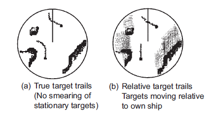
Trail: Echo trails show the movements of radar echoes relative or true to your vessel. The trails disappear over time (according to the "Trail Length" parameter). When set to "True" mode, only objects that are moving in reference to the water (such as another ship) will show a trail on the screen. Fixed objects on the water (such as buoys or a rock) will not show a trail even if your own ship is moving. When set to "relative" mode, any objects that move relative to your boat will leave a trail on the screen. So if your own ship is moving toward a stationary target (buoys for example), the target will leave a trail (smearing):
-
Radar Initial Setup: These settings are used to adjust the initial setup of the Radar. Note that this section will be limited if you are using a Furuno FAR radar (such as FAR2xx8) as these initial settings are performed from the Radar Processor directly. These settings are always linked to a specific Radar antenna. Make sure to select the correct Radar Hostname (from the drop down menu) before adjusting these settings.
-
-
Radar Host: Select the Radar detected on the network
-
Nickname: Enter the Radar Nickname that will be used in TimeZero
-
Antenna Position: Enter the Radar Antenna position
-
Antenna Height (Furuno DRS Radar only): Select the Radar Antenna height. This setting is used to automatically adjust the STC calibration.
-
TX Channel (Furuno DRS-NXT Radar only): Select the transmit frequency of the solid state transceiver.
-
Target Analyzer (Furuno DRS-NXT Radar only): Set to "Rain" when you want to see radar echo caused by rain to be displayed using a blue color when the Target Analyzer is enabled. Set to "Target" when you want to display rain echo just like any other non-moving target (using green echo).
-
Auto Acquire by Doppler (Furuno DRS-NXT Radar only): When this setting is enabled, the DRS-NXT will automatically acquire ARPA target based upon Doppler information (it will attempt to acquire any target that are moving at a closing velocity of 2 or more knot).
-
Antenna Heading Align: It is not always possible to install a radar so that the front of the radar is exactly parallel with the boat’s keel or center line. The Antenna Heading Align adjustment can compensate for this discrepancy. This process allows you to align the radar transceiver with the center line of the boat and only needs to be set once. Note that this is a different function than aligning your heading sensor. To adjust the Radar Antenna Alignment, it is best to display the Radar Work Space in "Head Up" mode and aim the bow of your vessel (during calm weather) at a buoy while underway. The buoy target should appear straight up on the Radar Screen.
-
Sector Blanking: This feature is used to indicate a zone where the radar does not transmit a pulse. This is necessary if:
-
Two or more radars are mounted within each other's beam;
-
There is a significant structure near the radar that causes strong returns, overwhelming the circuitry of the radar;
-
You wish to prevent radiating a particular zone of the radar (for example, your radar is mounted low on the fly bridge).
-
-
Antenna Rotation (Furuno DRS Radar only): When set to "Auto" the DRS antenna rotation will increase automatically in specific conditions (at lower range). Select "24RPM" if you want the DRS radar to spin at a constant regular rate.
-
Main Bang Suppression: Increase this setting to reduce the "main bang" (circle that appears at the center of the radar screen).
-
Radar Optimization (Furuno DRS only, not available for DRS-NXT): Press that button while underway when commissioning the radar (note that it is not recommended to perform a Radar Optimization in the harbor because of the strong echo return). Pressing that button will calibrate the radar. You only need to press that button once after installing the radar. Note that there will be no feedback (no confirmation window) when you press that button.
-
Set Hardware to Factory Default (Furuno DRS only): Click on this button to reset the DRS radar to its factory settings.
-
Radar User Presets: Click on this button to open the Radar Preset window that allows to store radar configuration. Please refer to Radar User Preset for more information.
-
ARPA Processing (Furuno Radar only): By default, the ARPA processing is performed inside the Furuno Radar Antenna. You can change this option to "TimeZero" to use the internal TimeZero ARPA algorithm instead.
-
Advanced ARPA Settings: These advanced ARPA settings affect how the internal TimeZero ARPA algorithm detects and tracks the target.
-
Note: To adjust the Maximum and Minimum blob size, it is recommended to enable "Display Plots" at the bottom of the Advanced ARPA Settings window. This will display the "plots" using blue circles on top of the radar overlay. Once the plots are displayed on screen, it is easy to adjust the filter size until you don't see any blue circles around the echoes caused by noise, but still see blue circles around real targets.
Note: To adjust the minimum echo strength, it is recommended to enable "Quantized Radar Display" at the bottom of the page. This will display the radar picture as seen by the ARPA algorithm. Adjust this filter until weak echoes caused by noise disappear.
-
Maximum blob size in square meters: A radar echo ("blob") that is bigger than the value of this setting will not be accepted as a valid ARPA target candidate ("Plot"). This setting is useful to reject landmass.
-
Minimum blob size in pixel: A radar echo ("blob") that has a smaller surface in pixel than the values specified will not be accepted as a valid ARPA target candidate ("Plot"). This setting is very useful to filter out noise or interferences that may create very small echoes on screen.
-
Minimum echo strength: This setting adjusts a pre-processing filter that removes weak echos from the picture used by the ARPA algorithm (blob detection algorithm). This setting is useful to remove noise (weak echo) but adjusting this value too high may create false "blob" (by breaking apart a strong large echo in multiple distinct smaller echoes).
-
Target Max Speed: This setting specifies the maximum speed of a target (50Kn by default). Decrease this value if you only want to track slower target (this will decrease the false detection rate).
-
Tracking Reactivity: TimeZero uses an advanced Kalman filter to smooth past target positions and predict the next target location. This setting adjusts the filter "responsiveness". The smaller the value, the longer the filter will take to react to sudden changes in target course. This means that targets turning fast or accelerating/stopping fast may be lost. But the advantages of a slower reactivity filter is that the COG/SOG of the target will be very stable (averaged) and its track will be very smooth. If the reactivity is increased, the filter will be quicker to react, but will cause the tracking to be "choppy" and COG and SOG to be less stable (varies quickly).
-
Target Min Acquire Scans: A target that is being acquired (displayed with dash contour) will be considered as a valid target (displayed with solid contour) when the corresponding underlying plot is present during the specified amount of consecutive antenna turn. If the echo (plot) disappears for one (or multiple) antenna turn before reaching the Target Min Acquire scans value, the counter is restarted (the target must be validated again during x consecutive antenna turn).
-
Target Max Acquire Scans: A target that is being acquired (displayed with dash contour) for too long (because the blob appears and disappears before reaching the minimum consecutive antenna turn) will automatically be dropped after reaching this value.
-
Target Min Lost Scans: A target that is already acquired (displayed with solid contour) will be considered as "Lost" if the underlying echo ("plot") disappears during the specified amount of consecutive antenna turn.
-
Display Plots: Displays the Radar Plots on screen. Plots are represented by blue circle and identify all the echoes whose shape could match a target. Pixel size and surface are also displayed next to the plots. This can help adjusting the ARPA filter.
-
Display Gate Distance: Displays the search gate (circle) on the chart around each target. The search gate is used to link new observations to a specific target. If an observation (plot) is outside of the search gate, it will not be used.
-
Quantized Radar Display: When this setting is enabled, the Radar Overlay will display the radar picture as seen by the ARPA processing algorithm. All echo will have the same value and will be "gated". This can be useful to temporary enable this mode when adjusting the "Minimum Echo Strength" parameter. Make sure to turn OFF this parameter when you are done.
-
-
Radar Status: This button opens a window displaying the radar antenna status. Pressing and holding the CTRL key while opening this window will allow you to reset the Transmit Time and the Power ON Time of the radar.