Initial Setup
-
Boat Length: Enter the vessel length
-
Boat Width: Enter the vessel width
-
Boat MMSI: Enter the vessel MMSI (identification). This field is automatically populated when connected to an AIS transmitter.
-
Boat Name: Enter the vessel name. This field is automatically populated when connected to an AIS transmitter.
-
Boat Registration Number: Enter the vessel registration number.
-
Boat Icon: Users can choose the shape of the boat icon when the plotter is used in 3D (the shape of the 2D icon is fixed and cannot be changed)
-
Static Icon Size: Users can choose the size of the 2D boat icon. Note that if you zoom to a very small range, the vessel icon size (in either 2D or 3D) will be displayed at its real scale (size) on the chart according to the "Boat Length" parameter.
-
Day Boat Icon Color: Allows to select the color of the boat icon and COG vector during the day
-
Night Boat Icon Color: Allows to select the color of the boat icon and COG vector during the night
-
Depth Display: Users can choose to display the depth below the waterline or below keel. This requires the user to enter proper values for "Keel Draft" and "Transducer Draft"
-
Transducer Draft Source: When set to "automatic", TimeZerowill try to use the offset sent by the instruments and revert to the offset set below if they are missing. When set to "hardware", will only use the offset received by the instruments (causing lack of data if the instruments are not sending the proper offset). When set to "manual", will only use the offset set below:
-
-
Transducer Draft: The value for "Transducer Draft" is always a positive value (enter the distance in between the water line and the position of the transducer).
-
Keel Draft: The value for "Keel Draft" is also a positive value (enter the distance in between the water line and the bottom of the Keel).
-
-
Radar Cursor Reference: When the Radar Cursor information is received from the NMEA0183 RSD sentence, this setting allows to adjust if the angle received from the radar is from North Up ("True") or Head Up ("Relative").
-
True Wind and VMG Calculation: When set to "Surface", Heading and Speed through Water will be used to compute True Wind and VMG if they are not received. When set to "Ground", Course Over Ground (COG) and Speed Over Ground (SOG) will be used instead. Make sure to adjust this selection to "Ground" if you only receive Apparent Wind and don't have a Heading Sensor and Speed sensor.
-
Allow Dead Reckoning: Allows TimeZero to activate the Dead Reckoning mode in case of GPS failure. Please refer to Dead Reckoning for more information.
-
CCRP: The CCRP (Consistent Common Reference Point) settings allows you to define offsets for GPS and Transducers (the Radar offset is setup from the Radar Options). As set by IMO regulations, the CCRP is the location at the ship icon, to which all horizontal measurements, such as target range, bearing, relative course/speed, closest point of approach, or time to closest point of approach are referenced. Usually this is the Wheelhouse position on the boat. When entering all the settings (for CCRP, GPS, Transducer,…) remember that the longitudinal positions are always positive (from Bow to Stern) while the lateral position is negative for Port and positive for Starboard (0 is the middle of the vessel)
-
Tank & Engine Manual Setup: Click on this button to setup your Tank NickNames and if they are used for fuel computation. TimeZero can decode up to four tank levels. Each tank sensor must have a different instance number. The Software will sort all of the tank sensors by ascending instance number. For tank that report a "Fuel" fluid type, you can select if they are used for fuel computation in TimeZero:
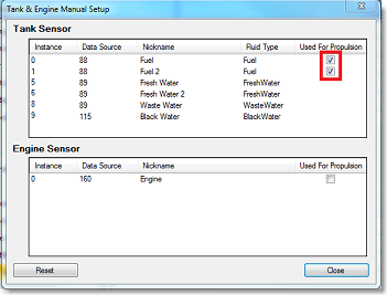
Note: This option only appears when a NMEA 2000 port (with Actisense NGT-1 or NGX-1 gateway) has been configured.
-
Furuno Satellite Compass Calibration: Press this button to open a window that will allow you to calibrate the Furuno Satellite Compass SC30, SC33 and SCX20. You can view and setup the Heading, Pitch and Roll offset. Note that the calibration only works when the compass is connected via the Actisense NGT1-USB or NGX1-USB (NMEA2000) and when the NMEA2000 output has been configured on the last page of the connection wizard.
-
Graphic Instruments Setup: Allows to enter the various Min/Max used for the Gauge NavData.
-
COG and SOG Damping: This setting can be useful when the GPS sends unreliable COG value (a COG that “jumps all over the place”) to smooth the value in TimeZero. Increasing this value will raise the COG & SOG averaging time (but will decrease the response time).
-
Wind Speed/Direction Damping: This setting smooths the wind data. Increasing this value will raise the Wind averaging time (but will decrease the response time).
-
Boat Speed Damping: This setting smooth the speed data. Increasing this value will raise the speed averaging time (but will decrease the response time). Increasing this setting usually result in stable ETA time.
-
Wind Speed / Direction Offset: Allows to offset the Wind Direction by adding or subtracting an angle value and by increasing or decreasing the speed by a percentage.
-
Boat Speed Offset: Allows to offset the boast speed (Speed Through Water) by increasing or decreasing the speed by a percentage.
-
Sea Surface Temperatur Offset: Allows to offset the SST by offsetting its value.
-
VHF Direction Finder
-
Minimal Signal Level (%): Adjust the threshold that is required for the DF Bearings to be displayed on the chart.
-
DF Bearing Timeout: Adjust the duration after which the DF Bearings will disappear from the chart if not continuously updated.
-
DF Bearing Color: Set the DF Bearing color on the chart (note that the alarm bearings will always be displayed in red).
-
-
Number of Monitors: Enables the user to use two or three monitors with TimeZero. This option will only be available when (at least) two monitors in extended mode are detected. When enable, TimeZero will put the second and third display to the right side of the primary monitor. If there is no monitor available to the right of the primary monitor (or not enough when selecting 3 monitors), TimeZero will use the monitor to the left side of the primary monitor. It is usually recommended to make the primary monitor of Windows the left most monitor.
-
Reset Dialog Box Position: Click this button to restore all dialog boxes (windows) to their default positions. This is useful if a dialog box (for example, the Properties window) has been moved to a disconnected monitor or pushed off the edge of the screen, making it no longer visible.
-
SeaLevel 110E/120E configuration: Press this button to configure the IP address of the SeaLevel Network IO. Please refer to the SeaLevel Network IO for more information.
-
Advanced Settings: These settings should not be adjusted unless instructed by Technical Support.
-
Convert Recorded Position to Trips...: Pressing this button will use the trail data (Own Ship Recorder database) to convert past position into Trips.